Wednesday, October 22, 2014
Browse »
home»
air
»
digital
»
Pengukur
»
RANGKAIAN
»
Suhu
»
Water Temperature Gauge Digital Network Diagram
![Rangkaian]() Skema rangkaian pengukur suhu air
Skema rangkaian pengukur suhu air
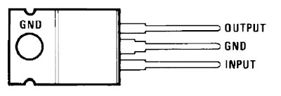
IC LM340A Temperature Gauge

Parameters IC LM340A
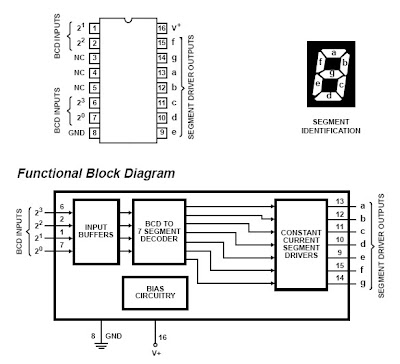
IC CA3161E Description

Absolute Maximum Ratings IC CA3161E
IC CA3162E Description

Absolute Maximum Ratings IC CA3162E
Water Temperature Gauge Digital Network Diagram
This circuit measures the water temperature. this circuit use IC CA3161 and CA3162 for control all, The Temperature Value can’t be keep always while no power supply as It hasn’t EEPROM to save. This circiut will be display for you monitoring only that is make sense to implement in water.
The IC CA3161 is a counter and 7segment LED driver to display amount of temperature on 7segments. About a temperature sensor is a diode which number 1N4148. This is like of the Car Radiator. Connect to the 5 Vdc power supply from Car Battery that you can use a LM7805 for +5Vdc regulation with low cost voltage regulator.
The IC CA3161 is a counter and 7segment LED driver to display amount of temperature on 7segments. About a temperature sensor is a diode which number 1N4148. This is like of the Car Radiator. Connect to the 5 Vdc power supply from Car Battery that you can use a LM7805 for +5Vdc regulation with low cost voltage regulator.
For the method of temperature measurement: first after application of at least 2 currents of a thermal sensor, including at least two output signals are generated calculating an analog signal to the temperature of the reaction at least two signals, the analog signal representative of temperature to the temperature sensors, a calibration, the calibration factor is calculated by applying the order of leastthree thermal sensor, and calibration of a gap in the temperature of the concept of analog signal, that the development gap-term is at least a series of parasite resistance to the thermal temperature sensor and the signal processing theanalog digital signal to a temperature reference value for the conversion of the reference value for the transition is consistent with the calibration.
IC LM340A Temperature Gauge
The LM340A monolithic 3-terminal positive voltage regulators employ internal current-limiting, thermal shutdown and safe-area compensation, making them essentially indestructible. If adequate heat sinking is provided, they can deliver over 1.0A output current.

Parameters IC LM340A
- Output Current: 1000 mA
- Output Voltage: 7.5, 12, 15, 8, 5 Volt
- Input Min Voltage: 7.5, 14.8, 10.5, 17.9 Volt
- Input Max Voltage: 35 Volt
- Temperature Min: 0 deg C
- Temperature Max: 70, 125 deg C
- RegType: Linear Regulator
IC CA3161E Description
The CA3161E is a monolithic integrated circuit that performs the BCD to seven segment decoding function and features constant current segment drivers. When used with the CA3162E A/D Converter the CA3161E provides a complete digital readout system with a minimum number of external parts.

Absolute Maximum Ratings IC CA3161E
- DC VSUPPLY (Between Terminals 1 and 10) . . . . . . . . . . . . . .+7.0V
- Input Voltage (Terminals 1, 2, 6, 7). . . . . . . . . . . . . . . . . . . . . .+5.5V
- Output Voltage
- Output “Off”. . . . . . . . . . . . . . . . . . . . . . . . . . . . . . . . . . . . . . . +7V
- Output “On” (Note 1) . . . . . . . . . . . . . . . . . . . . . . . . . . . . . . . +10V
IC CA3162E Description
The CA3162E are I2L monolithic A/D converters that provide a 3 digit multiplexed BCD output. They are used with the CA3161E BCD-to-Seven-Segment Decoder/Driver and a minimum of external parts to implement a complete 3-digit display. The CA3162AE is identical to the CA3162E except for an extended operating temperature range.

Absolute Maximum Ratings IC CA3162E
- DC Supply Voltage (Between Pins 7 and 14) . . . . . . . . . . . . . +7V
- Input Voltage (Pin 10 or 11 to Ground). . . . . . . . . . . . . . . . . . . 15V
- Temperature Range CA3162E. . . . . . . . . . . . . . . . . . . . . . . . . . .0 to 75oC
- Temperature Range CA3162AE . .. . . . . . . . . . . . . . . . . . . . . . -40oC to 85oC
- Maximum Junction Temperature . . . . . . . . . . . . . . . . . . . . . . . 150oC
- Maximum Storage Temperature Range . . . . . .. . . . . . . . . . . . .-65oC to 150oC
- Maximum Lead Temperature (Soldering 10s) . . . . . . . . . . . . . 300oC..
Subscribe to:
Post Comments (Atom)
No comments:
Post a Comment
Note: Only a member of this blog may post a comment.