Showing posts with label portable. Show all posts
Showing posts with label portable. Show all posts
Tuesday, September 23, 2014
Portable Guitar Amplifier Circuit

Portable Guitar Amplifier Circuit Parts:
R1______________22K 1/4W Resistor
C1______________10µF 25V Electrolytic Capacitor
C2_____________100nF 63V Polyester or Ceramic Capacitor
C3_____________220µF 25V Electrolytic Capacitor
IC1__________TDA7052 Audio power amplifier IC
J1,J2__________6.3mm Stereo Jack sockets (switched)
SPKR___________8 Ohm Loudspeaker (See Notes)
B1________________9V PP3 Battery or
3V Battery (2 x 1.5V AA, AAA Cells in series etc.)
Clip for PP3 Battery or socket for 2 x 1.5V AA or AAA Cells
Portable Guitar Amplifier Technical data:
Max output power: 1.5W @ 9V supply - 8 Ohm load; 60mW @ 3V supply - 8 Ohm load
Frequency response: Flat from 20Hz to 20kHz
Total harmonic distortion @ 100mW output: 0.2%
Max input voltage @ 3V supply: 8mV RMS
Minimum input voltage for Fuzz-box operation: 18mV RMS @ 3V supply
Current consumption @ 400mW and 9V supply: 200mA
Current consumption @ 250mW and 9V supply: 150mA
Current consumption @ 60mW and 3V supply: 80mA
Quiescent current consumption: 6mA @ 9V, 4mA @ 3V supply
Fuzz-box current consumption: 3mA @ 3V supply

Monday, October 7, 2013
Portable Solar Lantern
This portable solar lantern circuit uses 6 volt/5 watt solar panels are now widely available. With the help of such a photo-voltaic panel we can construct an economical, simple but efficient and truly portable solar lantern unit. Next important component required is a high power (1watt) white LED module.
When solar panel is well exposed to sunlight, about 9 volt dc available from the panel can be used to recharge a 4.8 volt /600 mAh rated Ni-Cd batterypack. Here red LED (D2) functions as a charging process indicator with the help of resistor R1. Resistor R2 regulates the charging current flow to near 150mA.
Solar Lantern Circuit Schematic
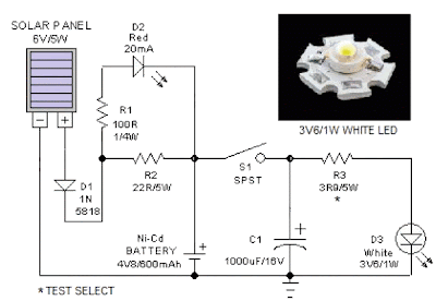
When solar panel is well exposed to sunlight, about 9 volt dc available from the panel can be used to recharge a 4.8 volt /600 mAh rated Ni-Cd batterypack. Here red LED (D2) functions as a charging process indicator with the help of resistor R1. Resistor R2 regulates the charging current flow to near 150mA.
Solar Lantern Circuit Schematic
Assuming a 4-5 hour sunlit day, the solar panel (150mA current set by the charge controller resistor R2) will pump about 600 – 750 mAh into the battery pack. When power switch S1 is turned on, dc supply from the Ni-Cd battery pack is extended to the white LED (D3). Resistor R3 determines the LED current. Capacitor C1 works as a buffer.
Note: After construction, slightly change the values of R1,R2 and R3 up/down by trial&error method, if necessary.
Friday, September 27, 2013
Audio Lineout Adaptor For Portable Radios
Here is an idea for a simple low-cost adapter that allows a portable FM radio (or MP3 player with FM tuner) to be connected to an external antenna and to audio equipment such as a hifi system or PC sound card. Portable FM radios and some MP3 players typically provide a 3.5mm stereo jack socket for the headphone connection, with the shield conductor of the headphone cable doubling as an antenna.
The problem:
Recently, the author bought a cheap FM radio with a USB connector, designed to be operated with a PC. The package included an audio cable with a 3.5mm stereo phone plug at each end. The plug that goes into the radio has an additional wire (about 2m long) hanging out of it, which is meant to serve as an indoor antenna. When using the supplied cable, the system suffered from poor radio reception (too much interference), and poor audio quality (lack of bass). The first problem was easily explained, as the radio was used in a marginal TV/FM reception area. When the cable was "buzzed out", the reason for the second problem became apparent.
There was no audio ground connection, as the cable screen is not connected to anything at the radio end! As mentioned, the antenna wire in these units is connected to the "common" terminal of the 3.5mm socket, which normally doubles as the audio signal return path. If this terminal were to be connected to the ground of external audio equipment, the antenna signal would be clobbered. Perhaps the designer of this cable assumed that an adequate audio ground connection would be made indirectly via the USB cable – a poor assumption!
 The challenge:
The challenge then was to provide a good antenna signal for the radio while at the same time making a good audio ground connection to external equipment. Preferably, this was to be achieved without relying on the USB connector (because not all FM radios have one) and without having to mess with the radio’s internal works. The accompanying circuit diagram shows how this can be achieved. The radio-frequency choke (L1) has a low impedance at audio frequencies, thereby making an audio ground path to the line output sockets from the radio’s antenna input ("common" terminal).
Conversely, the RFC presents a high impedance to the RF antenna signal, so preventing it from being shorted to ground. The antenna signal is coupled to the radio via two 220pF polystyrene (or ceramic) capacitors, which also block low-frequency interference (eg, mains hum). Note that the design relies on the capacitance in the audio cable to couple the antenna "ground" (cable shield) to the radio’s internal "ground".
Building it:
To build the adaptor, simply mount the parts in a small plastic box and wire up as shown. A suitable choke is available from Jaycar (Cat. No. LF-1534). The leads going to the 3.5mm plug should be no longer than about 100mm and need not be shielded. With a good TV/FM antenna, the author’s unit performed remarkably well, even in a poor FM reception area. The audio frequency response and signal-to-noise ratio were surprisingly good considering the low cost of the radio (about $40).
Continue reading...
The problem:
Recently, the author bought a cheap FM radio with a USB connector, designed to be operated with a PC. The package included an audio cable with a 3.5mm stereo phone plug at each end. The plug that goes into the radio has an additional wire (about 2m long) hanging out of it, which is meant to serve as an indoor antenna. When using the supplied cable, the system suffered from poor radio reception (too much interference), and poor audio quality (lack of bass). The first problem was easily explained, as the radio was used in a marginal TV/FM reception area. When the cable was "buzzed out", the reason for the second problem became apparent.
There was no audio ground connection, as the cable screen is not connected to anything at the radio end! As mentioned, the antenna wire in these units is connected to the "common" terminal of the 3.5mm socket, which normally doubles as the audio signal return path. If this terminal were to be connected to the ground of external audio equipment, the antenna signal would be clobbered. Perhaps the designer of this cable assumed that an adequate audio ground connection would be made indirectly via the USB cable – a poor assumption!

The challenge then was to provide a good antenna signal for the radio while at the same time making a good audio ground connection to external equipment. Preferably, this was to be achieved without relying on the USB connector (because not all FM radios have one) and without having to mess with the radio’s internal works. The accompanying circuit diagram shows how this can be achieved. The radio-frequency choke (L1) has a low impedance at audio frequencies, thereby making an audio ground path to the line output sockets from the radio’s antenna input ("common" terminal).
Conversely, the RFC presents a high impedance to the RF antenna signal, so preventing it from being shorted to ground. The antenna signal is coupled to the radio via two 220pF polystyrene (or ceramic) capacitors, which also block low-frequency interference (eg, mains hum). Note that the design relies on the capacitance in the audio cable to couple the antenna "ground" (cable shield) to the radio’s internal "ground".
Building it:
To build the adaptor, simply mount the parts in a small plastic box and wire up as shown. A suitable choke is available from Jaycar (Cat. No. LF-1534). The leads going to the 3.5mm plug should be no longer than about 100mm and need not be shielded. With a good TV/FM antenna, the author’s unit performed remarkably well, even in a poor FM reception area. The audio frequency response and signal-to-noise ratio were surprisingly good considering the low cost of the radio (about $40).
Subscribe to:
Posts (Atom)