Showing posts with label solar. Show all posts
Showing posts with label solar. Show all posts
Friday, June 6, 2014
4 Amps Photovoltaic Solar Charge Controller Circuit
The use of solar photovoltaic (PV) energy sources is increasing due to global warming concerns on the one hand, and cost effectiveness on the other. Many engineers involved in power electronics find solar power tempting and then addictive due to the ‘green’ energy concept. The circuit discussed here handles up to 4 amps of current from a solar panel, which equates to about 75 watts of power. A charging algorithm called ‘pulse time modulation’ is introduced in this design. The current flow from the solar panel to the battery is controlled by an N-channel MOSFET, T1. This MOSFET does not require any heat sink to get rid of its heat, as its RD-S(on) rating is just 0.024 Ω.
Schottky diode D1 prevents the battery discharging into the solar panel at night, and also provides reverse polarity protection to the battery. In the schematic, the lines with a sort-of-red highlight indicate potentially higher current paths. The charge controller never draws current from the battery—it is fully powered by the solar panel. At night, the charge controller effectively goes to sleep. In daytime use, as soon as the solar panel produces enough current and voltage, it starts charging the battery. The battery terminal potential is divided by resistor R1 and trimpot P1.
4 Amps Photovoltaic Solar Charge Controller Circuit Diagram

The resulting voltage sets the charge state for the controller. The heart of the charge controller is IC1, a type TL431ACZ voltage reference device with an open-collector error amplifier. Here the battery sense voltage is constantly compared to the TL431’s internal reference voltage. As long as the level set on P1 is below the internal reference voltage, IC1 causes the MOSFET to conduct. As the battery begins to take up the charge, its terminal volt- age will increase. When the battery reaches the charge-state set point, the output of IC1 drops low to less than 2 volts and effectively turns off the MOSFET, stopping all current flow into the battery.
Schottky diode D1 prevents the battery discharging into the solar panel at night, and also provides reverse polarity protection to the battery. In the schematic, the lines with a sort-of-red highlight indicate potentially higher current paths. The charge controller never draws current from the battery—it is fully powered by the solar panel. At night, the charge controller effectively goes to sleep. In daytime use, as soon as the solar panel produces enough current and voltage, it starts charging the battery. The battery terminal potential is divided by resistor R1 and trimpot P1.
4 Amps Photovoltaic Solar Charge Controller Circuit Diagram
The resulting voltage sets the charge state for the controller. The heart of the charge controller is IC1, a type TL431ACZ voltage reference device with an open-collector error amplifier. Here the battery sense voltage is constantly compared to the TL431’s internal reference voltage. As long as the level set on P1 is below the internal reference voltage, IC1 causes the MOSFET to conduct. As the battery begins to take up the charge, its terminal volt- age will increase. When the battery reaches the charge-state set point, the output of IC1 drops low to less than 2 volts and effectively turns off the MOSFET, stopping all current flow into the battery.
With T1 off, LED D2 also goes dark. There is no hysteresis path provided in the regulator IC. Consequently, as soon as the current to the battery stops, the output of IC1 remains low, preventing the MOSFET to conduct further even if the battery voltage drops. Lead-acid bat- tery chemistry demands float charging, so a very simple oscillator is implemented here to take care of this. Our oscillator exploits the negative resistance in transistors—first discovered by Leo Esaki and part of his studies into electron tunneling in solids, awarded with the Nobel Prize for Physics in 1973. In this implementation, a commonplace NPN transistor type 2SC1815 is used.
When the LED goes out, R4 charges a 22-μF capacitor (C1) until the voltage is high enough to cause the emitter-base junction of T2 to avalanche. At that point, the transistor turns on quickly and discharges the capacitor through R5. The voltage drop across R5 is sufficient to actuate T3, which in turn alters the reference voltage setting. Now the MOSFET again tries to charge the battery. As soon as the battery voltage reaches the charged level once more, the process repeats. A 2SC1815 transistor proved to work reliably in this circuit. Other transistors may be more temperamental—we suggest studying Esaki’s laureate work to find out why, but be cautioned that there are Heavy Mathematics Ahead.
As the battery becomes fully charged, the oscillator’s ‘on’ time shortens while the ‘off’ time remains long as determined by the timing components, R4 and C1. In effect, a pulse of current gets sent to the battery that will shorten over time. This charging algorithm may be dubbed Pulse Time Modulation. To adjust the circuit you’ll need a good digital voltmeter and a variable power supply. Adjust the supply to 14.9 V, that’s the 14.3 volts bat- tery setting plus approximately 0.6 volts across the Schottky diode.
Turn the trimpot until at a certain point the LED goes dark, this is the switch point, and the LED will start to flicker. You may have to try this adjustment more than once, as the closer you get the comparator to switch at exactly 14.3 V, the more accurate the charger will be. Disconnect the power supply from the charge controller and you are ready for the solar panel. The 14.3 V setting mentioned here should apply to most sealed and flooded-cell lead-acid batter- ies, but please check and verify the value with the manufacturer. Select the solar panel in such a way that its amps capability is within the safe charging limit of the battery you intend to use.
Resistors:
R1 = 15kΩ
R2,R3 = 3.3kΩ 1% R4 = 2.2MΩ
R5 = 1kΩ
P1 = 5kΩ preset
Capacitors:
C1 = 22μF 25V, radial
Semiconductors:
D1 = MBR1645G (ON Semiconductor) D2 = LED, 5mm
IC1 = TL431ACLP (Texas instruments)
T1 = IRFZ44NPBF (International Rectifier)
T2 = 2SC1815 (Toshiba) (device is marked: C1815)
T3 = BC547
Miscellaneous:
K1,K2 = 2-way PCB terminal block, lead pitch 5mm
Author: T. A. Babu (India - Elektor)

Simple Solar Relay Circuit Diagram
Build a Simple Solar Relay Circuit Diagram.With extended periods of bright sunshine and warm weather, even relatively large storage batteries in solar-power systems can become rather warm. Consequently, a circuit is usually connected in parallel with the storage battery to either connect a high-power shunt (in order to dissipate the excess solar power in the form of heat) or switch on a ventilation fan via a power FET, whenever the voltage rises above approximately 14.4 V. However, the latter option tends to oscillate, since switching on a powerful 12-V fan motor causes the voltage to drop below 14.4 V, causing the fan to be switched off. In the absence of an external load, the battery voltage recovers quickly, the terminal voltage rises above 14.4 V again and the switching process starts once again, despite the built-in hysteresis.
Simple Solar Relay Circuit Diagram

A solution to this problem is provided by the circuit shown here, which switches on the fan in response to the sweltering heat produced by the solar irradiation instead of an excessively high voltage at the battery terminals. Based on experience, the risk of battery overheating is only present in the summer between 2 and 6 pm. The intensity of the sunlight falling within the viewing angle of a suitably configured ‘sun probe’ is especially high precisely during this interval. This is the operating principle of the solar relay.
The trick to this apparently rather simple circuit consists of using a suitable combination of components. Instead of a power FET, it employs a special 12-V relay that can handle a large load in spite of its small size. This relay must have a coil resistance of at least 600 Ω, rather than the usual value of 100-200 Ω. This requirement can be met by several Schrack Components relays (available from, among others, Conrad Electronics). Here we have used the least expensive model, a type RYII 8-A printed circuit board relay. The light probe is connected in series with the relay. It consists of two BPW40 photo-transistors wired in parallel.
The type number refers to the 40-degree acceptance angle for incident light. In bright sunlight, the combined current generated by the two photo-transistors is sufficient to cause the relay to engage, in this case without twitching. Every relay has a large hysteresis, so the fan connected via the a/b contacts will run for many minutes, or even until the probe no longer receives sufficient light. The NTC thermistor connected in series performs two functions. First, it compensates for changes in the resistance of the copper wire in the coil, which increases by approximately 4 percent for every 10 ºC increase in temperature, and second, it causes the relay to drop out earlier than it otherwise would (the relay only drops out at a coil voltage of 4 V).
Depending on the intended use, the 220-Ω resistance of the thermistor can be modified by connecting a 100-Ω resistor in series or a 470-Ω resistor in parallel. If the photo-transistors are fastened with the axes of their incident-angle cones in parallel, the 40-degree incident angle corresponds to 2 pm with suitable solar orientation. If they are bent at a slight angle to each other, their incident angles overlap to cover a wider angle, such as 70 degrees. With the tested prototype circuit, the axes were oriented nearly parallel, and this fully met our demands. The automatic switch-off occurs quite abruptly, just like the switch-on, with no contact jitter. This behavior is also promoted by the NTC thermistor, since its temperature coefficient is opposite to that of the ‘PTC’ relay coil and approximately five times as large.
This yields exactly the desired effect for energizing and DE-energising the relay: a large relay current for engagement and a small relay current for disengagement. Building the circuit is actually straightforward, but you must pay attention to one thing. The photo transistors resemble color less LEDs, so there is a tendency to think that their ‘pinning’ is the same as that of LEDs, with the long lead being positive and the short lead negative. However, with the BPW40 the situation is exactly the opposite; the short lead is the collector lead. Naturally, the back-emf diode for the relay must also be connected with the right polarity. The residual current on cloudy days and at night is negligibly small.
Wednesday, December 18, 2013
Solar Cell Voltage Regulator
This device is designed to be a simple, inexpensive ‘comparator’, intended for use in a solar cell power supply setup where a quick ‘too low’ or ‘just right’ voltage indicator is needed. The circuit consists only of one 5V regulator, two transistors, two LEDs, five resistors, two capacitors, and one small battery. Although a 4-V battery is indicated, 4.5 V (3 alkalines in series) or 3.6 V (3 NiCd cells in series) will also work.
The specifications of voltage regulator IC1 are mainly determined by the size and number of the solar cells and the current pull of the equipment connected to the output. Here the low-drop 4805 is suggested but other regulators may work equally well as long as you observe the output voltage of the solar cells. Transistors T1 and T2 are complementary types i.e. one each of the pnp and npn variety.
Circuit diagram:

Although the ubiquitous BC557B (pnp) and BC547B (npn) are indicated, any small-signal equivalents out of the junk box will probably do. The values of voltage dividers R1/R6 and R3/R4 may need to be adjusted according to the type of transistor and its gain, or according to the desired voltage thresholds. Using the resistor values shown in the schematic, LED D2 turns on fully when the voltage is just above 5 volts.
LED D1 turns on when the voltage drops below 4.2 volts or so. Between those two thresholds, there is a sort of no man’s land where both LEDs are on dimly. A buzzer or other warning device could be connected across the terminals of LED D1 to give a more substantial warning if the voltage drops below operating limits. The current consumption of the circuit is about 20 mA at 5 V, and it decreases with the voltage supplied by the solar cells.
Continue reading...
The specifications of voltage regulator IC1 are mainly determined by the size and number of the solar cells and the current pull of the equipment connected to the output. Here the low-drop 4805 is suggested but other regulators may work equally well as long as you observe the output voltage of the solar cells. Transistors T1 and T2 are complementary types i.e. one each of the pnp and npn variety.
Circuit diagram:

Solar Cell Voltage Regulator Circuit Diagram
Although the ubiquitous BC557B (pnp) and BC547B (npn) are indicated, any small-signal equivalents out of the junk box will probably do. The values of voltage dividers R1/R6 and R3/R4 may need to be adjusted according to the type of transistor and its gain, or according to the desired voltage thresholds. Using the resistor values shown in the schematic, LED D2 turns on fully when the voltage is just above 5 volts.
LED D1 turns on when the voltage drops below 4.2 volts or so. Between those two thresholds, there is a sort of no man’s land where both LEDs are on dimly. A buzzer or other warning device could be connected across the terminals of LED D1 to give a more substantial warning if the voltage drops below operating limits. The current consumption of the circuit is about 20 mA at 5 V, and it decreases with the voltage supplied by the solar cells.
Reuben Posthuma
Monday, October 7, 2013
Portable Solar Lantern
This portable solar lantern circuit uses 6 volt/5 watt solar panels are now widely available. With the help of such a photo-voltaic panel we can construct an economical, simple but efficient and truly portable solar lantern unit. Next important component required is a high power (1watt) white LED module.
When solar panel is well exposed to sunlight, about 9 volt dc available from the panel can be used to recharge a 4.8 volt /600 mAh rated Ni-Cd batterypack. Here red LED (D2) functions as a charging process indicator with the help of resistor R1. Resistor R2 regulates the charging current flow to near 150mA.
Solar Lantern Circuit Schematic
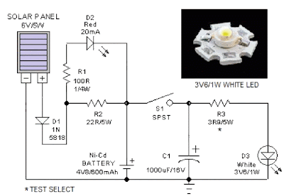
When solar panel is well exposed to sunlight, about 9 volt dc available from the panel can be used to recharge a 4.8 volt /600 mAh rated Ni-Cd batterypack. Here red LED (D2) functions as a charging process indicator with the help of resistor R1. Resistor R2 regulates the charging current flow to near 150mA.
Solar Lantern Circuit Schematic
Assuming a 4-5 hour sunlit day, the solar panel (150mA current set by the charge controller resistor R2) will pump about 600 – 750 mAh into the battery pack. When power switch S1 is turned on, dc supply from the Ni-Cd battery pack is extended to the white LED (D3). Resistor R3 determines the LED current. Capacitor C1 works as a buffer.
Note: After construction, slightly change the values of R1,R2 and R3 up/down by trial&error method, if necessary.
Thursday, September 12, 2013
Tracking Battery Charger IC Supports Solar Power Systems
Individual solar-panel systems produce dc power for remote applications while also storing energy in a rechargeable battery supported by a battery-charger IC. In non-utility grid applications solar panels produce dc power for emergency roadside telephones, navigation buoys, and other remote loads. Virtually all 12-V-system solar panels comprise a series of photovoltaic cells that have a maximum output power of less than 25 W.

In producing this power the solar-panel system uses a battery to provide power when the panel is “dark.” The rechargeable battery can supply power for long periods of time, requiring a charger that can properly operate a solar panel. Meeting this need is Linear Technology’s LT3652 monolithic buck-charger IC, which operates with a single solar panel.
The IC uses average-current-mode control-loop architecture to provide constant current/constant voltage (CC/CV) charge characteristics with a programmable charge current. The charger can be programmed to produce a 14.4-V float voltage. Housed in a 3- × 3-mm DFN-12 package, the IC can charge a variety of battery configurations, including up to three Li-Ion/Polymer cells in series, up to four Lithium Iron Phosphate (LiFePO4) cells in series, and sealed lead-acid batteries up to 14.4 V.
The IC uses average-current-mode control-loop architecture to provide constant current/constant voltage (CC/CV) charge characteristics with a programmable charge current. The charger can be programmed to produce a 14.4-V float voltage. Housed in a 3- × 3-mm DFN-12 package, the IC can charge a variety of battery configurations, including up to three Li-Ion/Polymer cells in series, up to four Lithium Iron Phosphate (LiFePO4) cells in series, and sealed lead-acid batteries up to 14.4 V.
Subscribe to:
Posts (Atom)