Showing posts with label transmitter. Show all posts
Showing posts with label transmitter. Show all posts
Friday, November 14, 2014
FM TRANSMITTER
This is a very interesting and simple project in the series of communication used to transmit noise free F.M. signal in the wide range up to 100 M using only one transistor. The transmitted message from F.M. transmitter circuit is received by the receiver having the facilities of F.M. channel.
Circuit Description
The entire circuit of F.M. transmitter is divided into three major stage i.e. oscillator, modulator and amplifier. The transmitting frequency of 88-108 MHz is generated by adjusting VC1. The input voice given to microphone is changed into electric signal and is given to base of transistor T1. Transistor T1 is used as oscillator which oscillates the frequency of 88-108 MHz. The oscillated frequency is depended upon the value R2, C2, L2 and L3. This transmitted signal from F.M. transmitter is received and tuned by F.M. receiver.
Circuit Diagram

Parts List
Resistors (all ¼-watt, ± 5% Carbon)
R1 = 180 KΩ
R2 = 10 KΩ
R3 = 15 KΩ
R4 = 4.7 KΩ
Capacitors
C1 = 10 KPF
C2 = 10 PF
C3 = 20 KPF
C4 = 0.001 µF
C5 = 1 µF/10V
C6 = 4.7 PF
C7 = 10 KPF
C8 = 3.3 PF
VC1 = 22 PF
Semiconductor
T1 = BF194B
Miscellaneous
MIC1 = Condenser mike
L1, L2 = 3 turns of 22 SWG wire around any thin pencil
L3 = 2 turns of 22 SWG wire around any thin pencil.

Friday, June 6, 2014
Beacon Transmitter Circuit Diagram
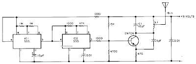
Simple Beacon Transmitter Circuit Diagram.This transmitter can be used for transmitter hunts, for remote key finding, or for radio telemetry in model rockets. It can be tuned to the two meter band or other VHF bands by charging Cl and Ll. 11 is four turns of #20 enameled wire air wound, 0.25 inch in diameter (use a drill bit), 0.2 inch long, center tapped. The antenna can be 18 inches of any type of wire. IC2 functions as an audio oscillator that is turned on and off by IC1 about once per second. The range of the transmitter is several hundred yards.
Simple Beacon Transmitter Circuit Diagram
Thursday, December 19, 2013
Simple FM Transmitter Circuit Schematic

Circuit Diagram

Circuit Description
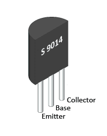
A S9014 NPN transistor is used here; you can use BC547 as an alternative of it. All the capacitor used in circuit is ceramic capacitor. Don’t be surprised with the supply voltage of 1.5 volt. Here you can use a single 1.5V AA battery cell, or a 3V battery that will be endurable for this this FM transmitter circuit. A small microphone used here is an electret condenser type microphone (see below). Must use at least a small antenna for a higher transmitting-range. Then try with a bigger antenna for increasing range.
Transistor S9014 Pinout
Electret condenser type microphone

If you have any confusion about capacitor value, check this.
SMD FM Transmitter
Let’s construct a low-power FM transmitter using surface-mount devices (SMD) that will be received with a standard FM radio. Soldering surface mounted devices is not so hard and actually is quite easy. There are many designs for small FM transmitters but they have some problems. First, you need an audio amplifier to get enough modulation. Second, the antenna is attached directly to the collector.
Third, the coil L must be wound by hand and adjusted by stretching. It all ads with a weak signal that tends to drift in frequency. In contrastm the transmitter schematic we present here eliminates some of those problems, using varactor diode for tuning and modulation, givind great sensitivity without an audio amplifier.

FM Transmitter – How it works
The figure below shows the schematic of the transmitter which consists of two stages: an oscillator and an output amplifier. Modulation is from an electret microphone but you can use a low power audio source.
Oscillator stage
Transistor Q1 is a Colpitts oscillator where the frequency is determined by the parallel resonant circuit formed by inductor L, varactor V1 and capacitors C7 and C8. Q1 is a common-collector amplifier where the power gain counts. V1 is actually a dual varactor that eliminate the possibility of forward conduction at the sinewave peaks.
The frequency of oscillation is set by adjusting the DC voltage on V1 with potentiometer R2. R4 and C3 form a low-pass filter to prevent RF from feeding back onto the DC. Capacitors C7 and C8 form an AC voltage divider to provide feedback at the emitter of Q1 to sustain oscillation. A necessary condition for oscillation to start is for the radio (C7+C8)/C7 to be sufficiently bigger than 1.
SMD transmitter circuit schematic

Frequency Modulation
Modulation is done by superimposing an audio signal from the electret mic onto the DC bias applied to V1. R3 and C1 form a low-pass filter to prevent RF from feeding back to the mic. R3, R4 and R2 form a votage divider for the audio.
Transmitter output stage
The output of the oscillator is fed through C9 to the Q2 emitter-follower. The output of Q2 drives the antenna through C11. The Q2 emitter-follower it ensures that the oscillator is not loaded down by the impedance of the antenna and it provides power gain to drive the antenna.
SMD Transmitter layout
The figure below shows the layout of the PCB and it uses surface-mounted devices like resistors and capacitors (non-polar devices). All the caps are size 0805 and all resistors are size 1206. use through-hole components for Q1, Q2, IC1 and V1. You can use an SOT-89 device for IC1 and an SOT-23 device for V1. Use MPSH10 or a transistor equivalent. Here you can learn how to solder smd chips.

The inductor
A coil would consist of two or three turns of wire but for this schematic we will use an inductor with loops of copper on the PCB. Such flat spiral inductor are common at these frequencies.
One formula for flat spiral inductors is:
flat spiral inductors formula where
L = inductance in uH
r = radius of coil (outer radius + inner radius divided by 2 ) inches
N = number of turns
d = depth of coil (outer radius minus inner radius) inches
Tuning range
While commercial FM band goes from about 88 MHz to 108 MHz, the L and C values used in this design allow tuning up to 100 MHz.
Transmitter testing
You will need a portable FM radio and an assistant. First, find an empty spot on the FM dial and set your radio about 30 feet away (9 meters). The radio’s volume control should not be set too high to prevend feedback. Next, power-up your transmitter and talk to yourself as you adjust the frequency with the trim-pot. When your assintant hears you, your transmitter is tuned. You might have to adjust the radio’s tuner slightly for best reception.
Have fun with it but remember that using the transmitter as a bugging device may not be legal in your country. To use the circuit as a wireless microphone, increase the value of R3. The transmitter range is about 100 feet (30 meters) inside a building.
Parts list

Continue reading...
Third, the coil L must be wound by hand and adjusted by stretching. It all ads with a weak signal that tends to drift in frequency. In contrastm the transmitter schematic we present here eliminates some of those problems, using varactor diode for tuning and modulation, givind great sensitivity without an audio amplifier.
FM Transmitter – How it works
The figure below shows the schematic of the transmitter which consists of two stages: an oscillator and an output amplifier. Modulation is from an electret microphone but you can use a low power audio source.
Oscillator stage
Transistor Q1 is a Colpitts oscillator where the frequency is determined by the parallel resonant circuit formed by inductor L, varactor V1 and capacitors C7 and C8. Q1 is a common-collector amplifier where the power gain counts. V1 is actually a dual varactor that eliminate the possibility of forward conduction at the sinewave peaks.
The frequency of oscillation is set by adjusting the DC voltage on V1 with potentiometer R2. R4 and C3 form a low-pass filter to prevent RF from feeding back onto the DC. Capacitors C7 and C8 form an AC voltage divider to provide feedback at the emitter of Q1 to sustain oscillation. A necessary condition for oscillation to start is for the radio (C7+C8)/C7 to be sufficiently bigger than 1.
SMD transmitter circuit schematic
Frequency Modulation
Modulation is done by superimposing an audio signal from the electret mic onto the DC bias applied to V1. R3 and C1 form a low-pass filter to prevent RF from feeding back to the mic. R3, R4 and R2 form a votage divider for the audio.
Transmitter output stage
The output of the oscillator is fed through C9 to the Q2 emitter-follower. The output of Q2 drives the antenna through C11. The Q2 emitter-follower it ensures that the oscillator is not loaded down by the impedance of the antenna and it provides power gain to drive the antenna.
SMD Transmitter layout
The figure below shows the layout of the PCB and it uses surface-mounted devices like resistors and capacitors (non-polar devices). All the caps are size 0805 and all resistors are size 1206. use through-hole components for Q1, Q2, IC1 and V1. You can use an SOT-89 device for IC1 and an SOT-23 device for V1. Use MPSH10 or a transistor equivalent. Here you can learn how to solder smd chips.
The inductor
A coil would consist of two or three turns of wire but for this schematic we will use an inductor with loops of copper on the PCB. Such flat spiral inductor are common at these frequencies.
One formula for flat spiral inductors is:
flat spiral inductors formula where
L = inductance in uH
r = radius of coil (outer radius + inner radius divided by 2 ) inches
N = number of turns
d = depth of coil (outer radius minus inner radius) inches
Tuning range
While commercial FM band goes from about 88 MHz to 108 MHz, the L and C values used in this design allow tuning up to 100 MHz.
Transmitter testing
You will need a portable FM radio and an assistant. First, find an empty spot on the FM dial and set your radio about 30 feet away (9 meters). The radio’s volume control should not be set too high to prevend feedback. Next, power-up your transmitter and talk to yourself as you adjust the frequency with the trim-pot. When your assintant hears you, your transmitter is tuned. You might have to adjust the radio’s tuner slightly for best reception.
Have fun with it but remember that using the transmitter as a bugging device may not be legal in your country. To use the circuit as a wireless microphone, increase the value of R3. The transmitter range is about 100 feet (30 meters) inside a building.
Parts list
Wednesday, October 2, 2013
Wire Tracer Transmitter
The circuit depicted here forms one half of a device that will prove extremely handy when tracing the path of electrical wiring in a building or to locate a break in a wire. The system is based on similar equipment that is used by technicians in telephone exchanges. The operation is straightforward. You require a generator that delivers an easily recognizable signal which, using a short antenna, is inductively coupled to a simple, but high gain, receiver. To create a useful transmitter it would suffice to build a simple generator based on a 555. But as the adjacent diagram shows, a 556 was selected instead. The second timer (IC1a) is used to modulate the tone produced by IC1b.
 The output frequency alternates between about 2100 Hz and 2200 Hz. This is a very distinctive test signal that is easily distinguished from any other signals that may be present. Resistor R6 is connected to a piece of wire, about ten centimeters long, that functions as the antenna. The ground connection (junction C2-C3) is connected to ground. When the antenna is connected directly to a cable, it is possible to determine at the other end of the cable, with the aid of the receiver, which conductor is which (don’t do this with live conductors!). The schematic for the matching receiver may be found elsewhere in this website.
Continue reading...
 The output frequency alternates between about 2100 Hz and 2200 Hz. This is a very distinctive test signal that is easily distinguished from any other signals that may be present. Resistor R6 is connected to a piece of wire, about ten centimeters long, that functions as the antenna. The ground connection (junction C2-C3) is connected to ground. When the antenna is connected directly to a cable, it is possible to determine at the other end of the cable, with the aid of the receiver, which conductor is which (don’t do this with live conductors!). The schematic for the matching receiver may be found elsewhere in this website.
Subscribe to:
Posts (Atom)