Showing posts with label automatic. Show all posts
Showing posts with label automatic. Show all posts
Sunday, November 2, 2014
AUTOMATIC AIRFLOW DETECTOR ELECTRONIC DIAGRAM
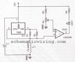
AUTOMATIC AIRFLOW DETECTOR ELECTRONIC DIAGRAM
Sensor used in this circuit is a bulb filament. If there is no airflow, the filament resistance would give low value. On the other hand, if there is airflow, the filament resistance would varies. The variation of the resistance is caused by the heat difference between filament. It also effects to the voltage variation passing through that filament. That voltage difference will be processed by LM339 op-amp and displayed by the LED.
Parts list :
- LED1 : LED 5mm
- IC1 volt regulator : LM7805
- Polar Capacitor C1 : 47 uF/15V
- Resistor R1 : 100 ohm
- Resistor R2 : 470 ohm
- Resistor R3 : 10k ohm
- Potensiometer R4 : 100k ohm
- Resistor R5 : 1k ohm
- IC2 op-amp : LM339
- Bulb filament
- Power supply/battery 12V

Saturday, September 13, 2014
New Automatic Load Sensing Power Switch
This schema will automatically switch on several mains-powered "slave" loads when a "master" load is turned on. For example, it will switch on the amplifier and CD player in a stereo system when the receiver is turned on. It works by sensing the current draw of the "master" device through a low value high wattage resistor using a comparator. The output of that comparator then switches on the "slave" relay. The schema can be built into a power bar, extension cord or power center to provide a convenient set of "smart" outlets that switch on when the master appliance is powered (turn on the computer monitor and the computer, printer and other peripherals come on as well).
New Automatic Load Sensing Power Switch Circuit Diagram
Parts |
| C1, C3 | 2 | 10uF 35V Electrolytic Capacitor | |
| C2 | 1 | 1uF 35V Electrolytic Capacitor | |
| R1 | 1 | 0.1 Ohm 10W Resistor | |
| R2 | 1 | 27K 1/2W Resistor | |
| R3, R4 | 1 | 1K 1/4W Resistor | |
| R5 | 1 | 470K 1/4W Resistor | |
| R6 | 1 | 4.7K 1/2W Resistor | |
| R7 | 1 | 10K 1/4W Resistor | |
| D1, D2, D4 | 3 | 1N4004 Rectifier Diode | |
| D3 | 1 | 1N4744 15V 1 Watt Zener Diode | |
| U1 | 1 | LM358N Dual Op Amp IC | |
| Q1 | 1 | 2N3904 NPN Transistor | |
| K1 | 1 | Relay, 12VDC Coil, 120VAC 10A Contacts | |
| S1 | 1 | SPST Switch 120AVC, 10A | |
| MISC | 1 | Board, Wire, Socket For U1, Case, Mains Plug, Socket |
- This schema is designed for 120V operation. For 240V operation, resistors R2 and R6 will need to be changed.
- A maximum of 5A can be used as the master unless the wattage of R1 is increased S1 provides a manual bypass switch.
- THis schema is not isolated from the mains supply. Because of this, you must exercise extreme caution when working around the schema if it is plugged in.
Tuesday, September 24, 2013
Automatic Heat Detector
This circuit uses a complementary pair comprising NPN metallic transistor T1 (BC109) and pnp germanium transistor T2 (AC188) to detect heat (due to outbreak of fire, etc) in the vicinity and energise a siren. The collector of transistor T1 is connected to the base of transistor T2, while the collector of transistor T2 is connected to relay RL1. The second part of the circuit comprises popular IC UM3561 (a siren and machine-gun sound generator IC), which can produce the sound of a fire-brigade siren. Pin numbers 5 and 6 of the IC are connected to the +3V supply when the relay is in energised state, whereas pin 2 is grounded. A resistor (R2) connected across pins 7 and 8 is used to fix the frequency of the inbuilt oscillator.
 The output is available from pin 3. Two transistors BC147 (T3) and BEL187 (T4) are connected in Darlington configuration to amplify the sound from UM3561. Resistor R4 in series with a 3V zener is used to provide the 3V supply to UM3561 when the relay is in energised state. LED1, connected in series with 68-ohm resistor R1 across resistor R4, glows when the siren is on. To test the working of the circuit, bring a burning matchstick close to transistor T1 (BC109), which causes the resistance of its emitter-collector junction to go low due to a rise in temperature and it starts conducting. Simultaneously, transistor T2 also conducts because its base is connected to the collector of transistor T1. As a result, relay RL1 energizes and switches on the siren circuit to produce loud sound of a fire-brigade siren.
Note.
Continue reading...
 The output is available from pin 3. Two transistors BC147 (T3) and BEL187 (T4) are connected in Darlington configuration to amplify the sound from UM3561. Resistor R4 in series with a 3V zener is used to provide the 3V supply to UM3561 when the relay is in energised state. LED1, connected in series with 68-ohm resistor R1 across resistor R4, glows when the siren is on. To test the working of the circuit, bring a burning matchstick close to transistor T1 (BC109), which causes the resistance of its emitter-collector junction to go low due to a rise in temperature and it starts conducting. Simultaneously, transistor T2 also conducts because its base is connected to the collector of transistor T1. As a result, relay RL1 energizes and switches on the siren circuit to produce loud sound of a fire-brigade siren.
Note.
- We have added a table to enable readers to obtain all possible sound effects by returning pins 1 and 2 as suggested in the table.
Subscribe to:
Posts (Atom)