Thursday, November 6, 2014
Power Supply Failure Alarm

Thursday, October 23, 2014
Power Supply Variable 1 3V 12 2V 1A Circuit

Description:
R2 to set the output voltage. The maximum current is determined by R3, over-current protection circuit inside the LM723 to detect the voltage on R3, if it reaches 0.65 V, the voltage output will be off her. So the current through R3 can not exceed 0.65 / R3 although output short-circuit in his.
C3 and C4 are ceramic capacitors, as much as possible directly soldered to the PCB, this is because the LM723 is prone to oscillation that is not cool.
LM723 works with 9.5V input voltage to 40 V DC and the LM723 can generate its own current of 150mA when the output voltage is not more than 6-7V under input voltage.
Specifications:
Output (value estimated):
Vmin = (R4 + R5) / (R5 * 1.3)
Vmax = (7.15 / R5) * (R4 + R5)
Imax = 0.65/R3
Max. Power on R3: 0.42/R3
Min. DC Input Voltage (pin 12 to pin 7): Vmax + 5
Component List:
B1 40V/2.5A
C1 2200uF (3300uF even better)
C2 4.7uF
C3 100nF
C4 1NF
C5 330nF
C6 100uF
Green LED D1
D2 1N4003
F1 0.2A F
F2 2A M
IC1 LM723 (in a DIL14 plastic package)
R1 1k
R2 Pot. 5k
R3 0.56R/2W
R4 3.3k
R5 4.7k
S1 250V/1A
T1 2N3055 on a heatsink 5K / W
TR1 220V/17V/1.5
Sunday, August 31, 2014
5 Volt power Supply

This is 5 volt power supply schema diagram.This schema regulates 5V.Input voltage is 6V to 12V.

Parts
# LM7805
# 100nF condensators
# 100uF condensator
# 10uF condensator
# N4002 diode
# LED
# 470 Ohm resistor
Saturday, December 21, 2013
Simple 0 50V 2A Bench Power Supply Circuit Diagram

Vlose p1=100uA*Rp1
This lose voltage regulate output voltage rate of output current is compare between reference voltage of P3 and lose voltage on R11.T3 is protecting short circuit with R11. For reduce out put voltage to 0v should parallel one resistor 470 ohm in out put. Minimum voltage is 0.4v. The maximum output voltage is fixed with R1b and should not become over of 50v. Therefore your transformer should give 36V, 3A with 4700uF capacitor. T6, T5, T7 need heatsilk.

R1b = read the text
R2 = 10 K
R3, R7 = 3.3 k
R4 = 390 Ohm
R5 = 47 K
R6 = 3.3 K 1Watt
R8 = 180 Ohm
R9, R10 = 0.47 Ohm 3Watt
R11 = 0.075 Ohm 2Watt
R12 = 470 Ohm
P1 = 500K liner potentiometer
P2 = 4.7 K potentiometer
P3 = 10 K potentiometer
C1 = 1nF
C2 = 10nF
C3 = 22nF
C4 = 47mF 63v electrolytic
C5 = 4700mF 80v electrolytic
T1, T2 = BC161
T3, T4 = BD141
T5 = BD241
T6, T7 = 2V3055
D1, D2 = 1N4148
D3, D4 = 1N4001
IC1, IC2 = LM10C
Friday, December 20, 2013
Antique Radio Dc Filament Supply Circuit Diagram

Thursday, December 19, 2013
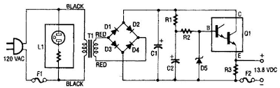
13 8Vdc 2A Regulated Power Supply Circuit Diagram
Tuesday, December 17, 2013
Soft Start For Switching Power Supply
When the supply cannot cope with this, it fails or the fuse blows. It is, therefore, advisable to disable the regulator at switch-on (via the on/off input). until the relevant capacitor has been charged. When the regulator then starts to draw current, the charging current has already dropped to a level which does not overload the voltage source.
Circuit diagram:

The circuit in the diagram provides an output voltage of 5 V and is supplied by a 24 V source. The regulator need not be disabled until the capacitor is fully charged: when the potential across the capacitor has reached a level of half or more of the input voltage, all is well. This is why the zener diode in the diagram is rated at 15 V. Many regulators produced by National Semiconductor have an integral on/off switch, and this is used in the present circuit.
The input is intended for TTL signals, and usually consists of a transistor whose base is accessible externally. This means that a higher switching voltage may be applied via a series resistor: the value of this in the present circuit is 22 kΩ. When the voltage across the capacitor reaches a level of about 17 V, transistor T1 comes on, whereupon the regulator is enabled.
Thursday, October 3, 2013
Computer Power Supply for Battery Charger
Some workbenches can’t help ending up looking like a rats nest of cables and equipment, so its always an advantage if a piece of mains equipment can be removed from somewhere to free up an extra mains socket. Here we are using the ubiquitous PC as a battery charger. An unused serial interface port can supply enough current to charge (or trickle charge) low-capacity Nickel Cadmium (NiCd) batteries. You could for example, use the batteries in a radio and charge them during use.

The three serial port connections TxD, DTR, and RTS, when not in use, are at –10 V and can supply a current of around 10 to 20mA (they are short-circuit protected). The circuit shown supplies a charging current of approximately 30mA. If it is necessary to alter the polarity of the charging circuit then it is a simple job to reverse the diodes and using software, switch the port signals +10 V. Those interested could also write a software routine to automatically recharge the batteries.
Source : www.extremecircuits.net
Friday, September 27, 2013
Variable DC Power Supply Circuit Diagram
Voltage Range: 0.7V to 24V, Current Range: 50mA to 2A
A variable dc power supply is one of the most useful tools on the electronics hobbyists workbench. This circuit is not an absolute novelty, but it is simple, reliable, "rugged" and short-proof, featuring variable voltage up to 24V and variable current limiting up to 2A. You can adapt it to your own requirements as explained in the notes below.
Circuit Diagram :

Variable DC Power Supply Circuit Diagram
Parts:
P1 = 500R
P2 = 10K
R1 = 2.2K-1/2w
R2 = 2.2K-1/2w
R3 = 330R
R4 = 150R
R5 = 1R-5W
C1 = 35V-3300uF
D1 = 1N5402
D2 = 1N5402
D3 = 5mm Red Led
C2 = 63V-1uF
Q1 = BC182
Q2 = BD139
Q3 = BC212
Q4 = 2N3055
SW1 = SPST Mains Switch
T1 = 36VCT-Transformer
Notes:
- P1 sets the maximum output current you want to be delivered by the power supply at a given output voltage.
- P2 sets the output voltage and must be a logarithmic taper type, in order to obtain a more linear scale voltage indication.
- You can choose the Transformer on the grounds of maximum voltage and current output needed. Best choices are: 36, 40 or 48V center-tapped and 50, 75, 80 or 100VA.
- Capacitor C1 can be 2200 to 6800µF, 35 to 50V.
- Q4 must be mounted on a good heatsink in order to withstand sustained output short-circuit. In some cases the rear panel of the metal box in which you will enclose the circuit can do the job.
- The 2N3055 transistor (Q4) can be replaced with TIP3055 type.
Source : www.redcircuits.com
Monday, September 23, 2013
Very Low Dropout Adjustable Breadboard Power Supply
 MIC2941 regulator has guaranteed 1.25A output
Low dropout, only 40mV - 400mV compared to 1.25V - 2.0V for LM317. This means you can use a wider range of output voltages including generating 3.3V from as low as 3.7V (such as 3 AAs or a lithium ion battery)!
Short circuit and overheating protection
Input diode to protect circuitry from negative voltages or AC power supplies.
2.1mm DC jack and terminal connector for voltage inputs
Two indicator LEDs for high and low voltages
Output selection switch to select from 3.3v, 5v and Adjustable
On-board potentiometer for adjusting voltage from 1.25V up to within 0.5V of the input voltage. (20V max)
On/Off switch for entire board
