Thursday, November 13, 2014
BC557 based Flashing Eyes circuit with explanation
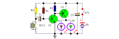 Two-LED-eyes follow the rhythm of music or speech, 3V Battery-operated device suitable for pins or badges
This circuit was purposely designed as a funny Halloween gadget. It should be placed to the rear of a badge or pin bearing a typical Halloween character image, e.g. a pumpkin, skull, black cat, witch, ghost etc. Two LEDs are fixed in place of the eyes of the character and will shine more or less brightly following the rhythm of the music or speech picked-up from surroundings by a small microphone. Two transistors provide the necessary amplification and drive the LEDs.
Parts:
R1 = 10K
R2 = 1M
R3 = 1K
C1 = 4.7uF-25V
C2 = 47uF-25V
D1 = 2mm LED
D2 = 2mm LED
Q1 = BC547
Q2 = BC557
B1 = 3V Battery
SW1 = SPST Switch
MIC1 = Electret Mic
Notes:
* Any general purpose, small signal transistor can be used for Q1 and Q2, but please note that R3 could require adjustment, depending on the gain of Q1. For medium gain transistors, the suggested value should do the job. High gain transistors will require a lower value for R3, i.e. about 390 – 470 Ohm. You can substitute R3 with a 1K Trimmer in order to set precisely the threshold of the circuit.
* Any LED type and color can be used, but small, 2mm diameter, high efficiency LEDs will produce a better effect.
* No limiting resistors are required for D1 and D2 even if this could seem incorrect.
* Stand-by current consumption of the circuit is about 1.5mA.
* Depending on dimensions of your badge, you can choose from a wide variety of battery types:
* 2 x 1.5 V batteries type: AA, AAA, AAAA, button clock-type, photo-camera type & others.
* 2 x 1.4 V mercury batteries, button clock-type.

Wednesday, October 29, 2014
Electronic Motor Starter Diagram Circuit
 Switch S1 is used to turn on the pump, while switch S2 is used to turn off the pump. While making over-/under-voltage setting, disconnect C2 temporarily. Capacitor C2 prevents relay chattering due to rapid voltage fluctuations. Regulator IC 7809 gives the 9V regulated supply to soft switch as well as the relay after filtering by capacitor C4. A suitable miniature circuit breaker is used for automatic over-current protection. Green LED (LED1) indicates that the motor is ‘on’ and red LED (LED2) indicates that the power is ‘on’. The motor is connected to the normally-open contact of the relay. When the relay energizes, the motor turns on.
Monday, October 27, 2014
STK4038 bassed 60 watt audio amplifier circuit project and explanation
Using the STK4038X audio amplifier IC, can be designed a very simple high power and efficiency audio power amplifier . This circuit is manufactured by Sanyo Corporation and will provide a output power of 60 watts on a 8 ohms load or 4 ohms load with 0.008% distortion .
The output power that is provided by this audio IC , can be more higher , but with more distortion.
If you will use a 8 ohms load you must power this audio amplifier project from a dual +/- 40 volts DC power supply and if you’ll use a 4 ohms load you must power this audio project form a dual +/- 33.5 volts DC power source.
To prevent over heating the STK4038X audio power IC must be heatsinked on a good heatsink .
Also you must use a very well filtered power supply ( a 10000uF capacitor will be fine for this audio project) .
Sunday, October 5, 2014
PIC16F628 Digital Clock Timer circuit and explanation
This clock timer uses a PIC16F628 microcontroller to display 3 and 1/2 digit time and control an external load. It can be programmed to time from 1 to 59 minutes. The clock includes a calendar with leap year and optional daylight savings adjustments. The timer output can be set from 1 to 59 minutes and manually switched on and off. The clock also has a correction feature that allows an additional second to be added every so many hours to compensate for a slightly slow running oscillator. The oscillator uses a common 32.768 KHz watch crystal and the frequency can be adjusted slightly with the 24pF capacitor on the right side of the crystal.