Wednesday, November 12, 2014
Build Power Amplifier LM3876 Simply and Powerfull Power Amplifier
The chip on which the amplifier is based, a Type LM3876, is a member of the Overture family from National Semiconductor, All members of this family are pin-compatible and mutually interchangeable. They are typified by an internal protection (called SPIKE). In practice, the diftection ference between them is the power output. The series was described on the basis of the LM3886 in an earlier issue*.
The PCB has been designed so what it can accommodate the LM3876 (50W) as well as the LM3886 (150W). Because of this, pin5 of the IC on the board is connected to the positive supply line. This connection is not needed for the LM3876, since its pin5 is not (internally) connected (NC).
The IC is located at the side of the board to facilitate fitting it to a heat sink as shown in the photograph.
An important aspect for optimum performance is the decoupling of the unregulated supply lines by C 7-10. All earth connections go to a single terminal on the board.
Air-cored inductor L1 consists of 13 turns of 1mm dia. enamelled copper wire with an inner diameter of 10mm. The completed inductor is pushed over R7 and its terminals soldered to those of the resistor.
All electrolytic capacitors must be mounted upright. The amplifier can be muted with a single-pole switch connected to the MUTE input (pin8). This function is enabled when the switch is open. If muting is not required, solder a wire bridge across the mute terminals on the board.
Boucherot network R6-C6 is not normally required in this application, but provision has been made for it for use in other applications.
According to the manufacturers, both chips are optimalized for a load of 8 Ohm. The output power is lower when a 4 Ohm load is used or when the supply voltage is reduced. When a 4 Ohm load is used, the SPIKE protection becomes active when the supply voltage is about 27V, resulting a in a reduction of the power output to 10W. This means that it is not advisable to use loudspeaker with an impedance <8 ohm.
For best result you can expand power amplifier using BPA-200 Amplifier
Part listResistor:
R1, R3 = 1 k
R2, R4, R5 = 18k
R6 = see text
R7 = 10R, 5 Watt
R8, R9 = 22k
Capacitors:
C1 = 2.2 uF
C2 = 220 uF, 160 V
C3 = 22 uF, 40 V
C4 = 47 pF
C5 = 100 uF, 40 V
C6 = see text
C7, C8 = 100 nF
C9, C10 = 1000 uF, 40 V
Inductors:
L1 = 0.7 uH - see text
Integrated circuits:
IC1 = LM3876T
Miscellaneous:
Heat sink for IC1 <1.5 k w-1
Single-pole switch - see text


Thursday, October 16, 2014
Build a Bass Treble Tone Control Circuit Diagram

- Wide supply voltage range, 9V to 16V
- Large volume control range, 75 dB typical
- Tone control, ±15 dB typical
- Channel separation, 75 dB typical
- Low distortion, 0.06% typical for an input level of 0.3 Vrms
- High signal to noise, 80 dB typical for an input level of 0.3 Vrms
- Few external components required
Vcc can be anything between 9V to 16V and the output capacitors are
10uF/25V electrolytic.
Friday, June 6, 2014
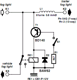
Build a Fog Lamp Switch Circuit Diagram
Fog Lamp Switch Circuit Diagram
Friday, December 20, 2013
Build a Positive input Negative output Charge pump Circuit Diagram
